> ## Documentation Index
> Fetch the complete documentation index at: https://docs.arc.cdata.com/llms.txt
> Use this file to discover all available pages before exploring further.
# Document Workflow Mappings
> Configure and test EDI document workflow mappings between partner documents and source or destination connectors in CData Arc.
export const siteNameShort = "Arc";
An important component of the TPMC is configuring the mapping between the incoming or outgoing EDI document and the connector where the data is stored or sent to.
*Incoming* mappings rely on receiving EDI documents from a partner over an MFT protocol, translating them from EDI to XML using an EDI standard, then mapping them to a destination connector such as a database.
*Outgoing* mappings rely on pulling data as XML from a source connector (such as a database), mapping that data to an XML representation of an EDI standard, converting the XML to EDI, then sending the EDI document out to a partner over an MFT protocol.
Document workflows are defined in two ways.
* From the [Partners](./edi-partners-tab#select-or-add-documents) tab, click the name of a partner, then choose the **Workflows** tab. See [Select or Add Documents](./edi-partners-tab#select-or-add-documents) for instructions on how to add documents and launch a workflow.
* From the [Documents](./edi-documents-tab) tab, click the name of an existing document, or choose **Add Document** to create a new one. See [Creating a Document from the Documents Tab](./edi-documents-tab#creating-a-document-from-the-documents-tab) for instructions on how to add a document and launch a workflow.
## Add Document Workflow
Defining document workflows includes the following steps:
1. Complete the **Add Document Workflow** screen.
1. When you add a document from the **Partners** tab, click **Add Workflow** to launch the document workflow. In this case, the fields on the **Add Document Workflow** screen are prefilled. You can change the document name, but all other fields are fixed.
2. When you add a document from the **Documents** tab, you must manually complete the fields on the **Add Document Workflow** screen.
2. [Select and configure the source or destination connector](#select-and-configure-the-source-or-destination)
3. [Configure the mapping](#configure-the-mapping). Mapping is applicable for all connectors except [File](../connectors/file), [AMQP](../connectors/amqp), and [Apache Kafka](../connectors/apachekafka) which do not use mapping. See [Document Workflow Without Mapping](./workflow-nomapping) for more information.
### Select and Configure the Source or Destination
When you create an *incoming* document, you must specify the destination connector where the data will be added. When you create an *outgoing* document, you must specify the source connector to pull the data from. The available connectors are the {siteNameShort} [Database](../connectors/database-connectors) and [Other](../connectors/other-connectors) connectors, the [File](../connectors/file) connector, the [Workspace Send](../connectors/workspace-send) connector (for incoming documents only), and the [Workspace Receive](../connectors/workspace-receive) connector (for outgoing documents only).
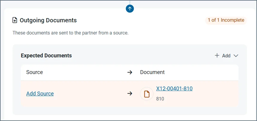
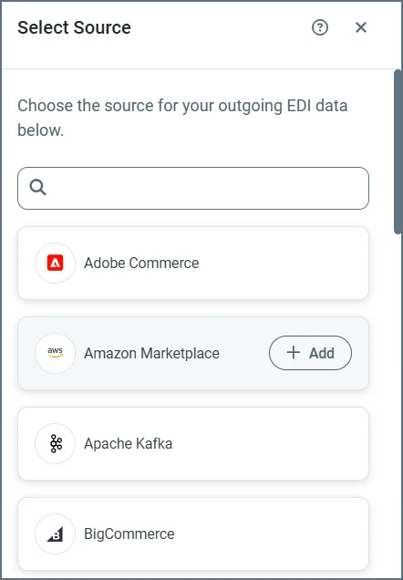
The following images show configuring a source for an outgoing document, but the same principles apply for incoming document destinations. In this example, the source is being defined from a partner's **Workflow** tab, but you can achieve the same result from the **Documents** tab.
1. From the **Workflow** tab, click **Add Source**.
 2. Highlight a connector in the **Select Source** list and click **Add**.
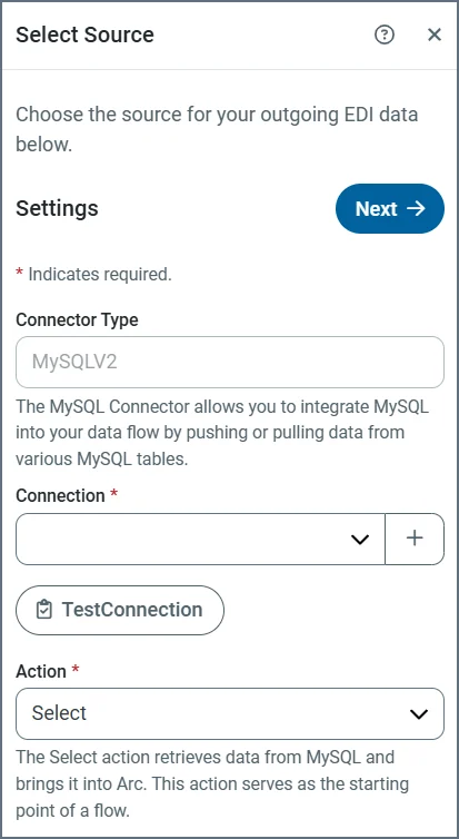
 3. Use the plus sign to create a new **Connection**, or use the dropdown to select an existing one.
 4. When you add a new connection, complete the following fields in the **Add Connection** window:
* Name
* Server
* Port
* User
* Password
* AWS Access Key (optional)
* AWS Secret Key (optional)
* AWS Role ARN (optional)
5. Click **Test Connection**.
6. The only action available for an outgoing document is `Select`, so when you have added and tested your connection, click **Next**. (The action for an incoming document is `Upsert`. See [Actions](#actions) for more information.)
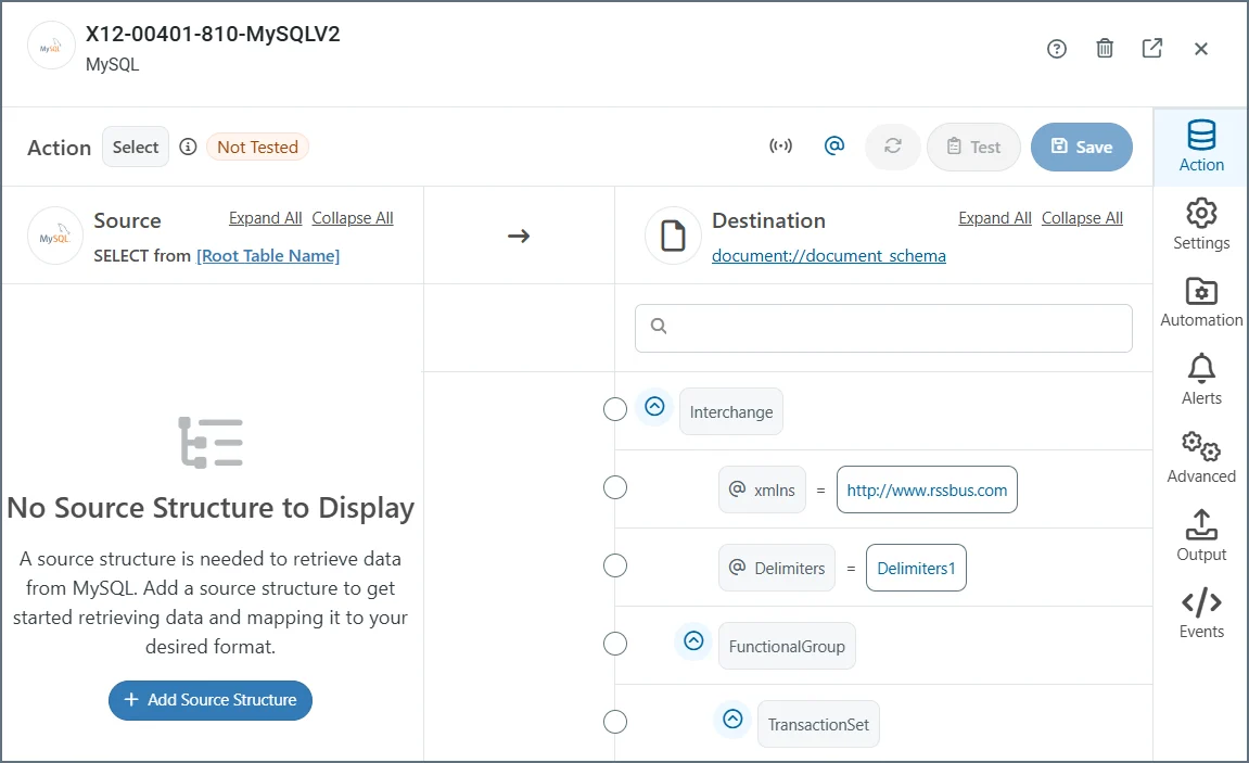
This opens the **Action** connector configuration tab, where you complete the mappings. See [Configure the Mapping](#configure-the-mapping) for instructions on how to use this tab.
4. When you add a new connection, complete the following fields in the **Add Connection** window:
* Name
* Server
* Port
* User
* Password
* AWS Access Key (optional)
* AWS Secret Key (optional)
* AWS Role ARN (optional)
5. Click **Test Connection**.
6. The only action available for an outgoing document is `Select`, so when you have added and tested your connection, click **Next**. (The action for an incoming document is `Upsert`. See [Actions](#actions) for more information.)
This opens the **Action** connector configuration tab, where you complete the mappings. See [Configure the Mapping](#configure-the-mapping) for instructions on how to use this tab.
 * Use the other configuration tabs (such as **Settings** and **Automation**) to complete the connector configuration. For details on the configuration options, click the question mark help icon to open the connector documentation.
* If you need to modify the connection after the original setup, use the **Connection** field on the **Settings** tab.
## Configure the Mapping
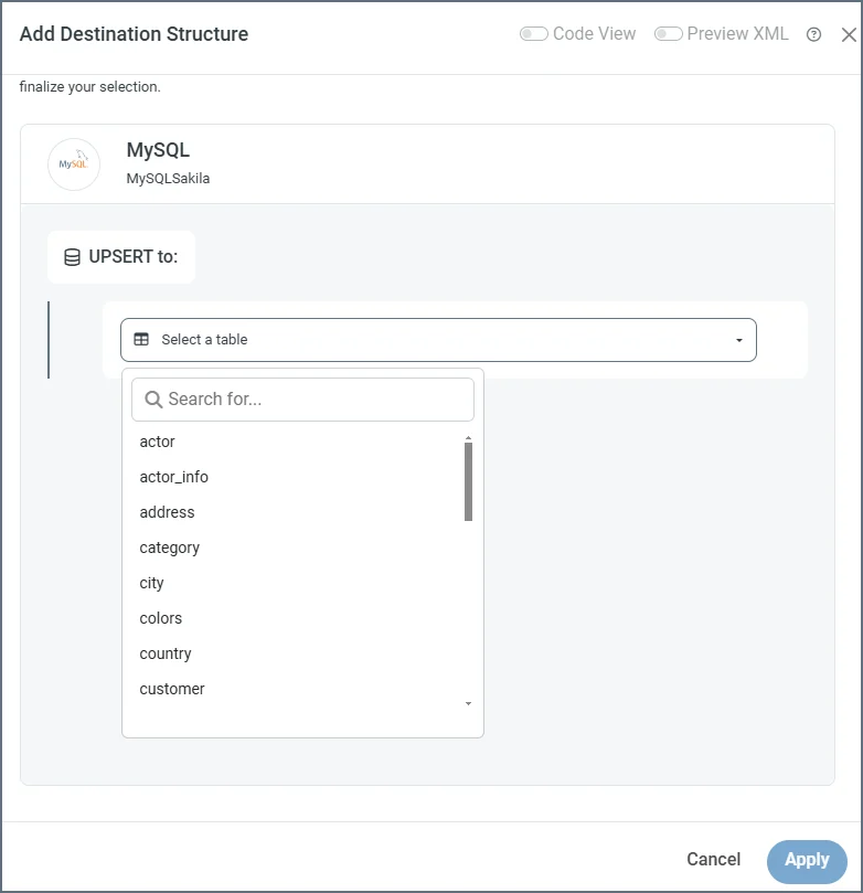
Once you have established the connection, you must select the table(s) that you need to map. If you're creating an incoming document, click **Add Destination Structure**. If you're creating an outgoing document, click **Add Source Structure**. This example shows adding a destination structure.
The following image of a completed mapping has been annotated to explain each element on the screen. Each number corresponds to a description below.
* Use the other configuration tabs (such as **Settings** and **Automation**) to complete the connector configuration. For details on the configuration options, click the question mark help icon to open the connector documentation.
* If you need to modify the connection after the original setup, use the **Connection** field on the **Settings** tab.
## Configure the Mapping
Once you have established the connection, you must select the table(s) that you need to map. If you're creating an incoming document, click **Add Destination Structure**. If you're creating an outgoing document, click **Add Source Structure**. This example shows adding a destination structure.
The following image of a completed mapping has been annotated to explain each element on the screen. Each number corresponds to a description below.
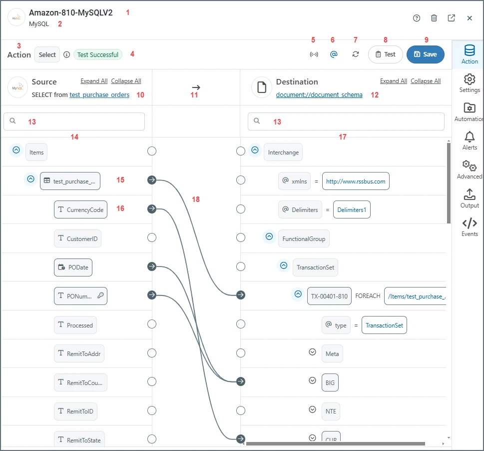 1. The document or connector name.
2. The connector type.
3. The action for the document. Values are **Upsert** for incoming documents, and **Select** for outgoing documents.
4. Test status of the mapping. Values are **Test Successful**, **Tested with Errors** or **Not Tested**.
5. Toggles XML streaming on or off. When on, the mapping engine drops the Document Object Model (DOM) for the current iteration of the top-most `Foreach` in the mapping after completing the loop. This can significantly improve performance for large XML documents. In situations where the mapping engine cannot resolve the mapping, it automatically toggles XML streaming off.
6. Toggles whether to show or hide the XML attributes.
7. Refreshes the mapping.
8. Opens the **Test Mapping** page. The test result is shown in #4. (See [Testing Mappings](#test-mappings) for more information.)
9. Saves the mapping.
10. The target table in the configured data source.
11. The direction of the mapping.
12. The schema of the EDI document (an 810 invoice in this example).
13. Search bars on the source and destination sides.
14. Structure of the source table.
15. The name of the table. This is also known as a table node.
16. A column in the table. This is also known as a column node.
17. The structure of the destination document.
18. Completed mappings.
Select a table from the dropdown.
1. The document or connector name.
2. The connector type.
3. The action for the document. Values are **Upsert** for incoming documents, and **Select** for outgoing documents.
4. Test status of the mapping. Values are **Test Successful**, **Tested with Errors** or **Not Tested**.
5. Toggles XML streaming on or off. When on, the mapping engine drops the Document Object Model (DOM) for the current iteration of the top-most `Foreach` in the mapping after completing the loop. This can significantly improve performance for large XML documents. In situations where the mapping engine cannot resolve the mapping, it automatically toggles XML streaming off.
6. Toggles whether to show or hide the XML attributes.
7. Refreshes the mapping.
8. Opens the **Test Mapping** page. The test result is shown in #4. (See [Testing Mappings](#test-mappings) for more information.)
9. Saves the mapping.
10. The target table in the configured data source.
11. The direction of the mapping.
12. The schema of the EDI document (an 810 invoice in this example).
13. Search bars on the source and destination sides.
14. Structure of the source table.
15. The name of the table. This is also known as a table node.
16. A column in the table. This is also known as a column node.
17. The structure of the destination document.
18. Completed mappings.
Select a table from the dropdown.
 To add more tables to the mapping, click the link to the first table, then click the **Add Child Table** arrow and select the next table.
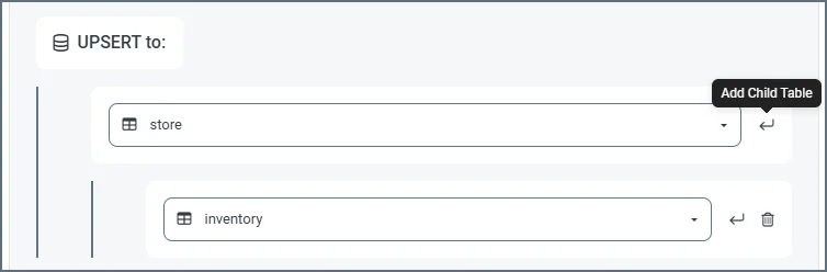 Repeat these steps until you have added all the required tables. As you make changes, the mapping page displays the latest table structure.
The mapping page enables you to create the links between the EDI document and the source or destination connector. For incoming documents, the EDI document structure is in the left pane and the connector table structure is in the right pane. For outgoing documents it's the reverse, as you can see in the annotated image above.
See [Configure the Mapping](../mapping/mapping-config) in the [Mapping](../mapping) documentation for detailed instructions on how to use the mapping editor.
To edit a previously saved mapping, click **EDI > Documents**, then click the document name. In the **Document Workflow** section, click the link to the connector in the **Document Destination** (for incoming documents) or the **Document Source** (for outgoing documents).
### Understanding Source and Destination
As mentioned previously, when you create an *incoming* document, you must specify the destination connector where the data will be sent. The EDI document structure is in the left pane and the connector table structure is in the right pane.
When you create an *outgoing* document, you must specify the source connector to pull the data from. Here, the connector table structure is in the left pane and the EDI document structure is in the right pane.
{siteNameShort} provides a number of ways in which you can manipulate the information in the table and document structures. See [Table Structure Nodes](#table-structure-nodes) and [Document Nodes](#document-nodes) for details.
To change the document schema, or to upload a template file that represents the source or destination XML structure, click the link to the document schema and choose **Upload File**. This is helpful if your partner provides you with a sample document of what they are expecting to send and/or receive. For example, if your partner provides you with a sample X12 850, you can convert it into XML by running it through an [X12 connector](../connectors/x12) in `X12 to XML` mode in a regular workspace. Then you can upload the output XML as a template file.
Repeat these steps until you have added all the required tables. As you make changes, the mapping page displays the latest table structure.
The mapping page enables you to create the links between the EDI document and the source or destination connector. For incoming documents, the EDI document structure is in the left pane and the connector table structure is in the right pane. For outgoing documents it's the reverse, as you can see in the annotated image above.
See [Configure the Mapping](../mapping/mapping-config) in the [Mapping](../mapping) documentation for detailed instructions on how to use the mapping editor.
To edit a previously saved mapping, click **EDI > Documents**, then click the document name. In the **Document Workflow** section, click the link to the connector in the **Document Destination** (for incoming documents) or the **Document Source** (for outgoing documents).
### Understanding Source and Destination
As mentioned previously, when you create an *incoming* document, you must specify the destination connector where the data will be sent. The EDI document structure is in the left pane and the connector table structure is in the right pane.
When you create an *outgoing* document, you must specify the source connector to pull the data from. Here, the connector table structure is in the left pane and the EDI document structure is in the right pane.
{siteNameShort} provides a number of ways in which you can manipulate the information in the table and document structures. See [Table Structure Nodes](#table-structure-nodes) and [Document Nodes](#document-nodes) for details.
To change the document schema, or to upload a template file that represents the source or destination XML structure, click the link to the document schema and choose **Upload File**. This is helpful if your partner provides you with a sample document of what they are expecting to send and/or receive. For example, if your partner provides you with a sample X12 850, you can convert it into XML by running it through an [X12 connector](../connectors/x12) in `X12 to XML` mode in a regular workspace. Then you can upload the output XML as a template file.
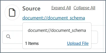 Browse to the template file, then click **Upload Template File**.
#### Actions
Two actions are available when you configure a connector:
* Upsert is the action for incoming documents. This action inserts or updates data into the target destination table. If a record already exists in the destination table, an update is performed on the existing data using the values provided from the input.
* Select is the action for outgoing documents. This action retrieves data from the target data source.
### Table Structure Nodes
This section describes the options available in the mapping pane that displays the source or destination table structure. There are two types of nodes in the structure: table nodes and column nodes. Table nodes represent the table itself and column nodes represent the columns in the table.
#### Table Nodes
Table nodes are indicated with a table icon. When you hover over a table node, you have two additional options:
* Click the funnel icon to open the **Add Mapping Conditions** page which enables you to add filter conditions to the mapping. See [Using the Condition Editor](../mapping/mapping-condition-editor) for more information. (Only available for incoming document mappings.)
* Click the ellipses to open a list of options for that table node:
* **Rename Table** lets you change the name of the node.
* **Remove Table** removes the node.
* **Table Settings** opens an edit window that lets you select which columns to include in the mapping, and whether to apply [filters](#filter-groups). (Only available for outgoing document mappings.)
* **Edit Columns** opens an edit window that lets you select which columns to include in the mapping. (Only available for incoming document mappings.)
* **Add** opens a new list of nodes that you can create and use in your mappings. (Only available for incoming document mappings.) The options are:
* **Add Header** creates a header node that you can map a value to. The mapped value is not included in the output file but is added as a header on the mapping output message.
* **Add Loop** creates a loop node above the selected node and that node becomes nested within the loop node. See [Mapping Loops](../mapping/mapping-config#mapping-loops) for more information.
* **Add Condition** lets you add conditions to destination nodes so that data is only upserted to the destination if the condition is true. See [Using the Condition Editor](../mapping/mapping-condition-editor) for details.
* **Add Code Script** opens the **Add Script** window where you can name the script node and supply custom {siteNameShort}Script.
* **Add Variable** creates a variable node below the selected node. See [Variables](../mapping/mapping-node-value-editor#variables) for more information.
#### Column Nodes
Column nodes represent columns in a table. Every column node has a type, which is the column's datatype in the database. There are seven different datatypes, each one with its own symbol. Hover over a column to see its datatype, size, and whether it is nullable. The datatypes are:
* String
* Number
* Binary
* Boolean
* Date
* Time
* Date and Time
Hover over a column row and click the ellipses to open a list of options for that node:
* **Rename Column** lets you change the name of the node.
* **Remove Column** removes the node.
* **Add** opens a new list of nodes that you can create and use in your mappings. (Only available for incoming document mappings.) The options are:
* **Add Header** creates a header node that you can map a value to. The mapped value is not included in the output file but is added as a header on the mapping output message.
* **Add Loop** creates a loop node above the selected node and that node becomes nested within the loop node. See [Mapping Loops](../mapping/mapping-config#mapping-loops) for more information.
* **Add Code Script** opens the **Add Script** window where you can name the script node and supply custom {siteNameShort}Script.
* **Add Variable** creates a variable node below the selected node. See [Variables](../mapping/mapping-node-value-editor#variables) for more information.
* **Add Tracking** adds [tracked headers](../getting-started/administration/activity#tracked-headers) to the mapping. When a node has tracking enabled, it displays a compass icon.
### Document Nodes
Document nodes refer to the nodes on other side of the mapping: the non-database side. These nodes are not explicitly related to a data source (a table with columns) but rather represent the EDI data in an XML structure. These nodes are mapped to for outgoing documents and mapped from for incoming documents.
For outgoing documents (using the Select action), click the funnel icon to open the **Add Mapping Conditions** page which enables you to add filter conditions to the mapping. See [Using the Condition Editor](../mapping/mapping-condition-editor) for more information. Click the ellipses to use the following options in the destination document:
* **Rename Node** lets you change the name of the node.
* **Edit XPath** lets you edit the node XPath (only on elements already mapped as `Foreach`).
* **Delete Node** lets you delete the node from the document.
* **Add Node**
* **Add Sibling** adds a node at the same level as the selected node.
* **Add Attribute** adds an attribute to the selected node.
* **Add Child** adds a node as a child of the selected node.
* **Add Header** creates a header node that you can map a value to. The mapped value is not included in the output file but is added as a header on the mapping output message.
* **Add Loop** creates a loop node above the selected node and that node becomes nested within the loop node. See [Mapping Loops](../mapping/mapping-config#mapping-loops) for more information.
* **Add Condition** opens the [Condition Editor](../mapping/mapping-condition-editor) where you can add conditions so that data is only upserted to the destination if the condition is true.
* **Add Code Script** opens the **Add Script** window where you can name the script node and supply custom {siteNameShort}Script.
* **Add Variable** creates a variable node below the selected node. See [Variables](../mapping/mapping-node-value-editor#variables) for more information.
* **Cut Node** cuts the selected node from its current location.
* **Copy Node** copies the selected node.
* **Paste as Child** pastes the cut or copied node as a child of the selected node.
For incoming documents (using the Upsert action), click the ellipses in the source document structure to use the following options:
* **Rename Node** lets you change the name of the node.
* **Delete Node** lets you delete the node from the document.
* **Add Node**
* **Add Sibling** adds a node at the same level as the selected node.
* **Add Attribute** adds an attribute to the selected node.
* **Add Child** adds a node as a child of the selected node.
* **Cut Node** cuts the selected node from its current location.
* **Copy Node** copies the selected node.
* **Paste as Child** pastes the cut or copied node as a child of the selected node.
You can also use **Edit Node** to open the **Edit Node Value** page. See [Using the Node Value Editor](../mapping/mapping-node-value-editor).
## Test Mappings
Once you have configured the mapping, you should test it. Click the **Test Mapping** button at the top of the page. The following image shows testing an incoming document.
Browse to the template file, then click **Upload Template File**.
#### Actions
Two actions are available when you configure a connector:
* Upsert is the action for incoming documents. This action inserts or updates data into the target destination table. If a record already exists in the destination table, an update is performed on the existing data using the values provided from the input.
* Select is the action for outgoing documents. This action retrieves data from the target data source.
### Table Structure Nodes
This section describes the options available in the mapping pane that displays the source or destination table structure. There are two types of nodes in the structure: table nodes and column nodes. Table nodes represent the table itself and column nodes represent the columns in the table.
#### Table Nodes
Table nodes are indicated with a table icon. When you hover over a table node, you have two additional options:
* Click the funnel icon to open the **Add Mapping Conditions** page which enables you to add filter conditions to the mapping. See [Using the Condition Editor](../mapping/mapping-condition-editor) for more information. (Only available for incoming document mappings.)
* Click the ellipses to open a list of options for that table node:
* **Rename Table** lets you change the name of the node.
* **Remove Table** removes the node.
* **Table Settings** opens an edit window that lets you select which columns to include in the mapping, and whether to apply [filters](#filter-groups). (Only available for outgoing document mappings.)
* **Edit Columns** opens an edit window that lets you select which columns to include in the mapping. (Only available for incoming document mappings.)
* **Add** opens a new list of nodes that you can create and use in your mappings. (Only available for incoming document mappings.) The options are:
* **Add Header** creates a header node that you can map a value to. The mapped value is not included in the output file but is added as a header on the mapping output message.
* **Add Loop** creates a loop node above the selected node and that node becomes nested within the loop node. See [Mapping Loops](../mapping/mapping-config#mapping-loops) for more information.
* **Add Condition** lets you add conditions to destination nodes so that data is only upserted to the destination if the condition is true. See [Using the Condition Editor](../mapping/mapping-condition-editor) for details.
* **Add Code Script** opens the **Add Script** window where you can name the script node and supply custom {siteNameShort}Script.
* **Add Variable** creates a variable node below the selected node. See [Variables](../mapping/mapping-node-value-editor#variables) for more information.
#### Column Nodes
Column nodes represent columns in a table. Every column node has a type, which is the column's datatype in the database. There are seven different datatypes, each one with its own symbol. Hover over a column to see its datatype, size, and whether it is nullable. The datatypes are:
* String
* Number
* Binary
* Boolean
* Date
* Time
* Date and Time
Hover over a column row and click the ellipses to open a list of options for that node:
* **Rename Column** lets you change the name of the node.
* **Remove Column** removes the node.
* **Add** opens a new list of nodes that you can create and use in your mappings. (Only available for incoming document mappings.) The options are:
* **Add Header** creates a header node that you can map a value to. The mapped value is not included in the output file but is added as a header on the mapping output message.
* **Add Loop** creates a loop node above the selected node and that node becomes nested within the loop node. See [Mapping Loops](../mapping/mapping-config#mapping-loops) for more information.
* **Add Code Script** opens the **Add Script** window where you can name the script node and supply custom {siteNameShort}Script.
* **Add Variable** creates a variable node below the selected node. See [Variables](../mapping/mapping-node-value-editor#variables) for more information.
* **Add Tracking** adds [tracked headers](../getting-started/administration/activity#tracked-headers) to the mapping. When a node has tracking enabled, it displays a compass icon.
### Document Nodes
Document nodes refer to the nodes on other side of the mapping: the non-database side. These nodes are not explicitly related to a data source (a table with columns) but rather represent the EDI data in an XML structure. These nodes are mapped to for outgoing documents and mapped from for incoming documents.
For outgoing documents (using the Select action), click the funnel icon to open the **Add Mapping Conditions** page which enables you to add filter conditions to the mapping. See [Using the Condition Editor](../mapping/mapping-condition-editor) for more information. Click the ellipses to use the following options in the destination document:
* **Rename Node** lets you change the name of the node.
* **Edit XPath** lets you edit the node XPath (only on elements already mapped as `Foreach`).
* **Delete Node** lets you delete the node from the document.
* **Add Node**
* **Add Sibling** adds a node at the same level as the selected node.
* **Add Attribute** adds an attribute to the selected node.
* **Add Child** adds a node as a child of the selected node.
* **Add Header** creates a header node that you can map a value to. The mapped value is not included in the output file but is added as a header on the mapping output message.
* **Add Loop** creates a loop node above the selected node and that node becomes nested within the loop node. See [Mapping Loops](../mapping/mapping-config#mapping-loops) for more information.
* **Add Condition** opens the [Condition Editor](../mapping/mapping-condition-editor) where you can add conditions so that data is only upserted to the destination if the condition is true.
* **Add Code Script** opens the **Add Script** window where you can name the script node and supply custom {siteNameShort}Script.
* **Add Variable** creates a variable node below the selected node. See [Variables](../mapping/mapping-node-value-editor#variables) for more information.
* **Cut Node** cuts the selected node from its current location.
* **Copy Node** copies the selected node.
* **Paste as Child** pastes the cut or copied node as a child of the selected node.
For incoming documents (using the Upsert action), click the ellipses in the source document structure to use the following options:
* **Rename Node** lets you change the name of the node.
* **Delete Node** lets you delete the node from the document.
* **Add Node**
* **Add Sibling** adds a node at the same level as the selected node.
* **Add Attribute** adds an attribute to the selected node.
* **Add Child** adds a node as a child of the selected node.
* **Cut Node** cuts the selected node from its current location.
* **Copy Node** copies the selected node.
* **Paste as Child** pastes the cut or copied node as a child of the selected node.
You can also use **Edit Node** to open the **Edit Node Value** page. See [Using the Node Value Editor](../mapping/mapping-node-value-editor).
## Test Mappings
Once you have configured the mapping, you should test it. Click the **Test Mapping** button at the top of the page. The following image shows testing an incoming document.
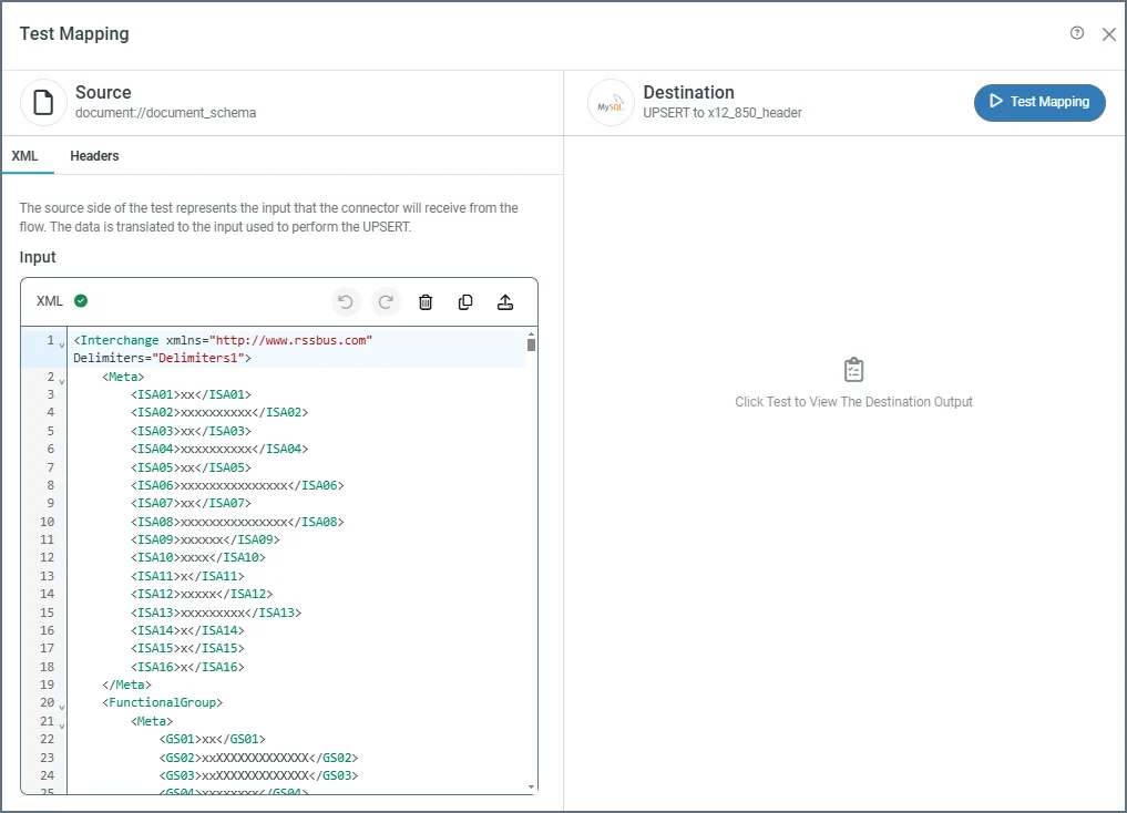 The source side of the test page has two tabs: **XML** and **Headers** (the **Headers** tab is only available on incoming documents). The source is populated with the XML representation of the document or table structure to test, but you can edit it as necessary. For incoming documents, click the **Headers** tab to add any headers you want to use in the mapping (see [Tracked Headers](../getting-started/administration/activity#tracked-headers) for more information). When you are ready, click **Test Mapping**.
Test result indicators appear on the partner **Workflow** page and on the mapping itself. The values on the mapping are **Test Successful**, **Tested with Errors** or **Not Tested**. The **Workflow** page shows a check for successful tests, a brown exclamation mark for untested mappings, and a red exclamation for tests with errors. Hover over the icons for details about the errors.
When you test incoming documents, you are testing with live data. When you click **Test Mapping**, {siteNameShort} tries to perform the `upsert` after it tests the mapping.
## Using Filters
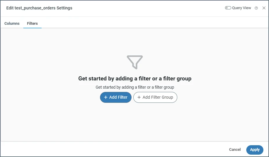
If you need to filter the data that the connector selects in a source table structure, click the ellipses and choose **Table Settings**, then click the **Filters** tab. The **Edit \ Settings** window opens, where you can define individual filters and filter groups.
The source side of the test page has two tabs: **XML** and **Headers** (the **Headers** tab is only available on incoming documents). The source is populated with the XML representation of the document or table structure to test, but you can edit it as necessary. For incoming documents, click the **Headers** tab to add any headers you want to use in the mapping (see [Tracked Headers](../getting-started/administration/activity#tracked-headers) for more information). When you are ready, click **Test Mapping**.
Test result indicators appear on the partner **Workflow** page and on the mapping itself. The values on the mapping are **Test Successful**, **Tested with Errors** or **Not Tested**. The **Workflow** page shows a check for successful tests, a brown exclamation mark for untested mappings, and a red exclamation for tests with errors. Hover over the icons for details about the errors.
When you test incoming documents, you are testing with live data. When you click **Test Mapping**, {siteNameShort} tries to perform the `upsert` after it tests the mapping.
## Using Filters
If you need to filter the data that the connector selects in a source table structure, click the ellipses and choose **Table Settings**, then click the **Filters** tab. The **Edit \ Settings** window opens, where you can define individual filters and filter groups.
 ### Creating a Filter Rule
To create a filter, follow these steps:
1. Click **Add Filter**.
2. In the drop-down list for the new rule, choose the column that you want to filter.
3. Choose the filtering condition. The available filtering conditions depend on the data type for the column you select.
4. If your filtering condition requires a value, enter that value in the blank value field. If your filtering condition does not require a value (for example, if you choose **Is Null**), the value field disappears.
For example, you could create a filter on a column named Author that only selects values that contain Smith. In this example, the column is **Author**, the condition is **Contains**, and the value is **Smith**.
### Filter Groups
You can apply multiple filters to your table by clicking **Add Filter**. Filters are separated by groups, and all filters belong to the same group by default. You can create multiple groups to separate filters by clicking **Add Group**.
Each filter in a group interacts with the others based on the options you select at the top of the group:
* Use the **NOT** toggle to invert the filter conditions. For example, in the **Author** filter example above, enabling the **NOT** toggle instructs the connector to select Author values that do *not* contain **Smith**.
* Select **AND** or **OR** to determine the group logic for multiple filters.
* If you select **AND**, every filter in the group must be true for the filter conditions to be met.
* If you select **OR**, at least one filter in the group must be true for the filter conditions to be met. Multiple filter can be met, and the results are the same as if only one were met.
### Using Query View
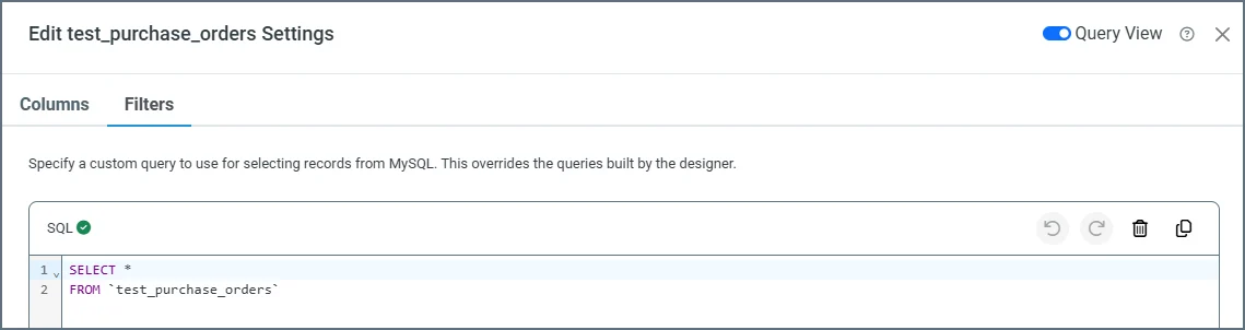
Toggle on **Query View** to write a custom SQL query that selects data from your data source. This overrides any queries created in the designer.
### Creating a Filter Rule
To create a filter, follow these steps:
1. Click **Add Filter**.
2. In the drop-down list for the new rule, choose the column that you want to filter.
3. Choose the filtering condition. The available filtering conditions depend on the data type for the column you select.
4. If your filtering condition requires a value, enter that value in the blank value field. If your filtering condition does not require a value (for example, if you choose **Is Null**), the value field disappears.
For example, you could create a filter on a column named Author that only selects values that contain Smith. In this example, the column is **Author**, the condition is **Contains**, and the value is **Smith**.
### Filter Groups
You can apply multiple filters to your table by clicking **Add Filter**. Filters are separated by groups, and all filters belong to the same group by default. You can create multiple groups to separate filters by clicking **Add Group**.
Each filter in a group interacts with the others based on the options you select at the top of the group:
* Use the **NOT** toggle to invert the filter conditions. For example, in the **Author** filter example above, enabling the **NOT** toggle instructs the connector to select Author values that do *not* contain **Smith**.
* Select **AND** or **OR** to determine the group logic for multiple filters.
* If you select **AND**, every filter in the group must be true for the filter conditions to be met.
* If you select **OR**, at least one filter in the group must be true for the filter conditions to be met. Multiple filter can be met, and the results are the same as if only one were met.
### Using Query View
Toggle on **Query View** to write a custom SQL query that selects data from your data source. This overrides any queries created in the designer.